
The first prompt was “can you design a robot arm that I can 3d print the housing from easy to get electronics and motors online”.
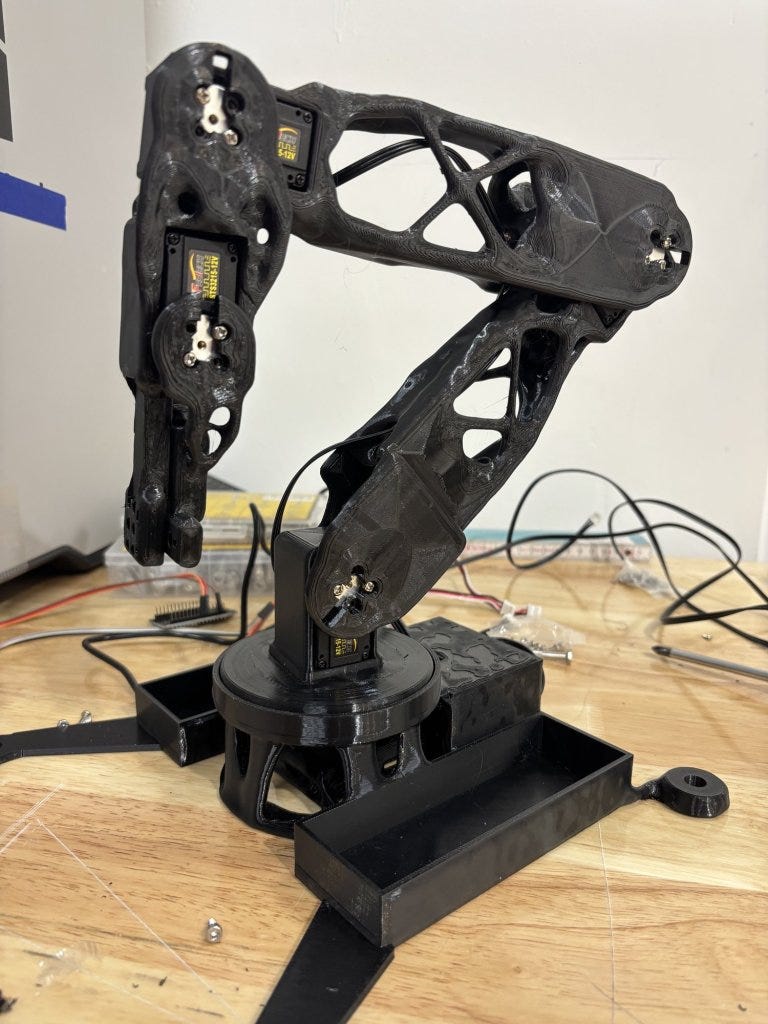
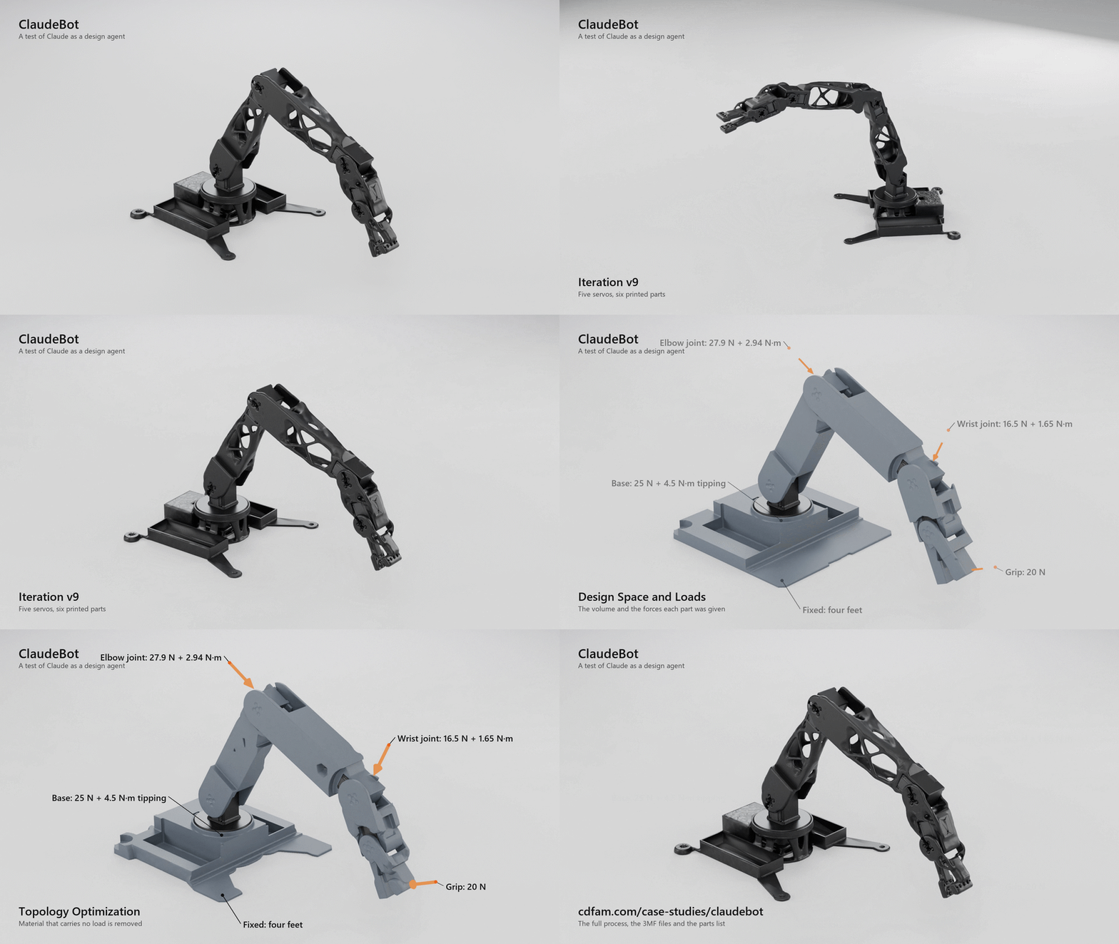
Fifteen days later iteration three (technically V9) of the arm on my bench: six printed parts, five serial bus servos, 200 mm links, a gripper. It moves on every joint and draws with a pen, badly. It does not play chess yet.
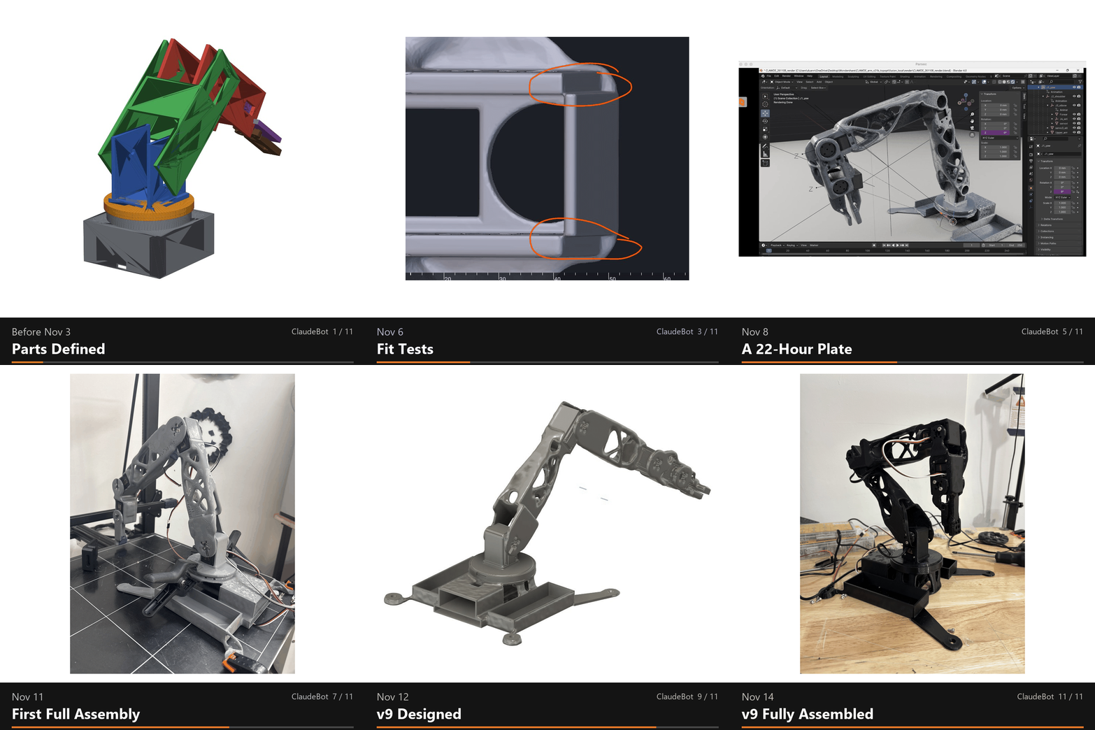
I did not manually 3D model any aspect of the arm, I did not specify the loads for topology optimisation and I did not in any way program the functionality. Every part was defined, optimized, checked, sliced and logged by Claude, working from plain-language prompts with photos, videos and marked-up screenshots as feedback.
My role was to define the outcome/intent I wanted, pay for components it specified, press Print, assemble the parts and report what went wrong.
Why Do This
I have been VERY skeptical of the whole ‘Text-to-CAD’ effort since it first emerged with the hype producing crude, useless meshes with no engineering or physics awareness for the past couple of years.
I kept on trying them with the same basic prompt of asking to design a VESA screen mount which is pretty simple, well documented as an engineering standard. Most of them were complete trash until less than a year ago when I was able to design a VESA mount in Grasshopper with Raven as an AI agent with some success.

So I kept on trying with each new release of the foundational models, burning tokens and getting nowhere until two weeks ago…
The project, ClaudeBot, is a test of Claude as a design and engineering agent: how far plain-language direction can carry a real assembly from definition through optimization, printing and bench testing. The arm is the test piece.
For context, my background is industrial design, so I do know how to 3D model things to at least look like they might work. I have no training or real experience in mechanical engineering, simulation or robotics. I have worked for both Autodesk and nTop in more hand waving/business and marketing roles, so I know what the software can do. But there is no way I could not have driven this design to this level myself. zero chance.
What is SUPER IMPORTANT here is that this whole project is driven by requirements and design intent, often poorly communicated, just like in the real world. The Agent had to interpret what I wanted, and use the tools available (Fusion, nTop + 3D Printer) to engineer a solution, specify parts it could not make.
Also super important is that EVERY MISTAKE IS TRACKED in real-time. If I poorly define a requirement, give ambiguous responses or change my mind three times, it is tracked, if Claude does not secure a servo, allows a disconnected strut, makes an assumption that fails to meet criteria. This is all tracked and auditable (and hopefully remembered as a skill for both of us).
How many current engineering processes really have this kind of visibility and accountability?
So, it is not perfect every time, we are currently printing v10 of the whole assembly in just over two weeks and what is really super important to note.
This is the worst AI empowered engineering will ever be, it is only going to get better.
The Workflow
Claude Code runs on a 2022 Dell G16 7620 Windows laptop with 16GB of RAM, as that is where the CAD software runs, I mostly reach by remote desktop from a MacBook Air or a phone. From there it drives everything else:
An Autodesk Fusion trial license for the interface geometry, the joints and the assembly interference checks.
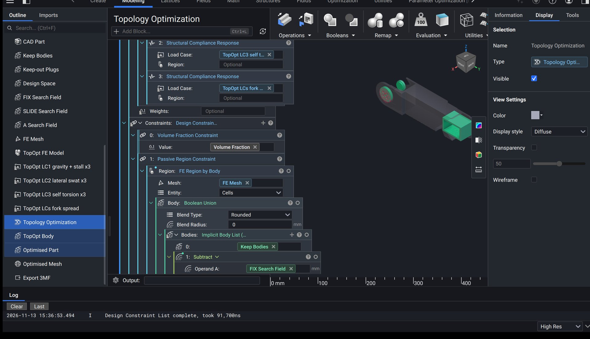
nTop, run headless from the command line, for topology optimization. Nobody touched the GUI except to inspect.
Python with OpenCascade and manifold3d to restore exact holes and mating faces after optimization.
Bambu Studio for slicing, with the parts printed in PETG on a Bambu Lab H2S.
Blender for renders and motion studies.
A second Claude conversation wrote the control software and runs the arm.
How the Shape Is Decided
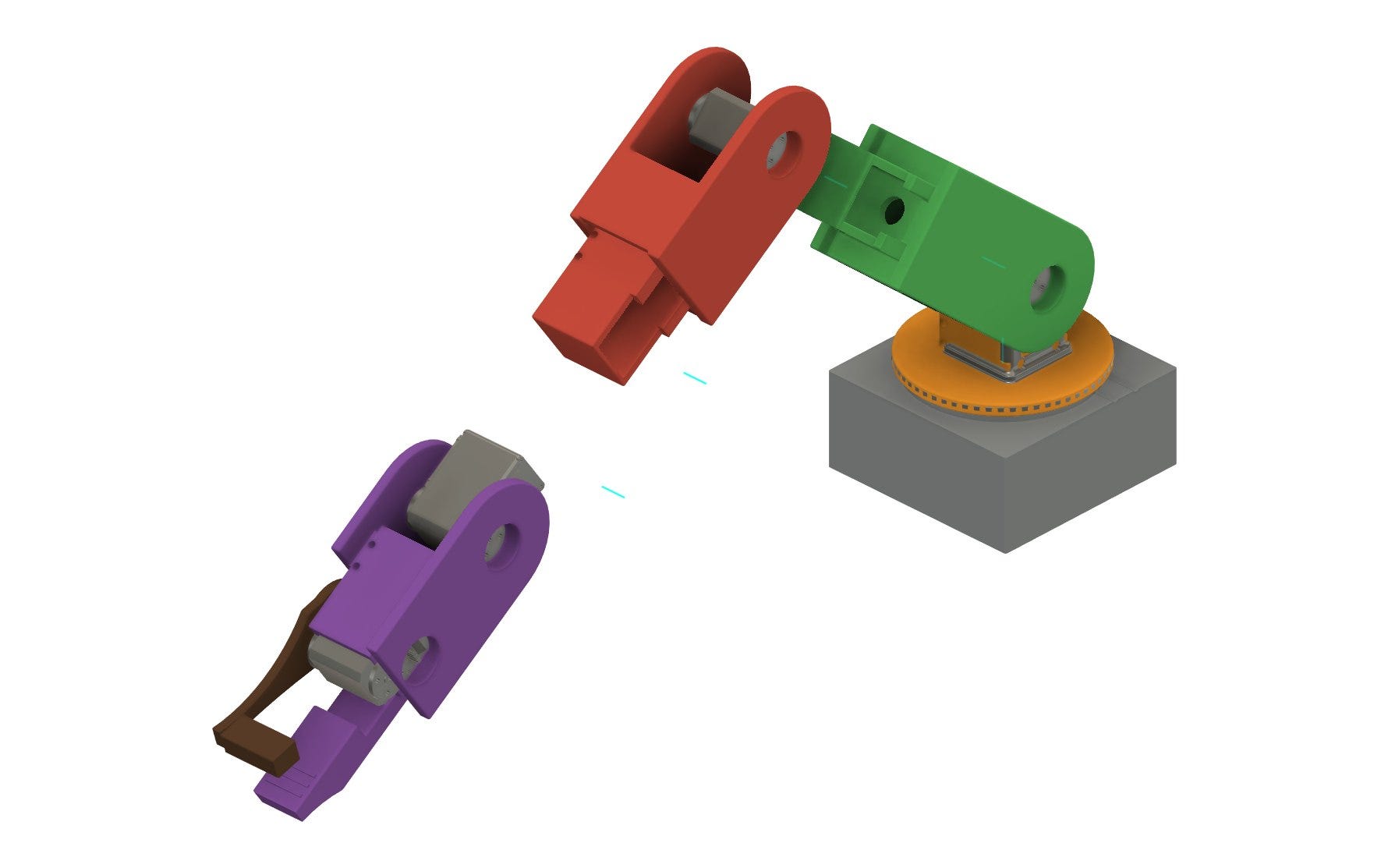
Each structural part is the output of an optimization that is given a volume it may use, regions it must keep, regions it must avoid, a material, restraints and loads that are all calculated by Claude, based on the servos it specified.
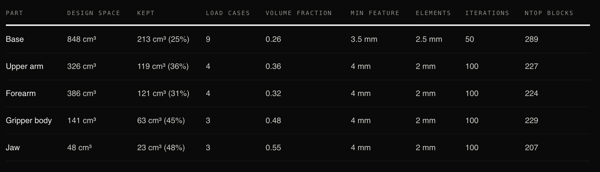
I as the human gave feedback when things either did not work, or looked bad based on my understanding of physics, and aesthetics (which are kinda the same thing here).
What Went Wrong (and whose fault it was)
About fifty issues are logged (so far), each with a date and an owner. Most trace to two causes: unclear instructions from me and unchecked assumptions from Claude.
The arm was designed around a 35 mm box standing in for the servo. When the first full plate came off the printer after 22 hours, not one joint could be assembled without blue artists tape holding it together.
Servos were not held in place by any fasteners
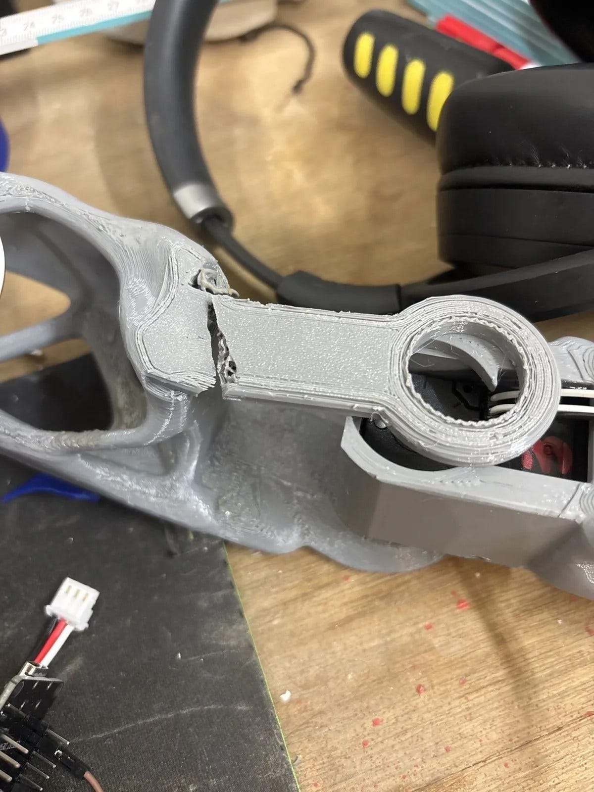
Connection arms had zero tolerance for assembly and snapped attempting to connect them.
I specified the base by sketch, then by adjective, then as an octopus holding onto a rock. That cost five optimization runs. The octopus was hella ugly.
Claude named a file “final”. Nothing has been called final since.
I ran the first servo test with the power supply unplugged. It was late.
The control software spent a day drawing distorted shapes because it was working from link lengths two versions old. The ‘design instance of Claude’ had never handed the new geometry over to the ‘programming instance of Claude’.
The turntable sits on the output gear of one servo and tips under the weight of the arm. This is the most serious fault on the current build.
How Many Tokens It Took
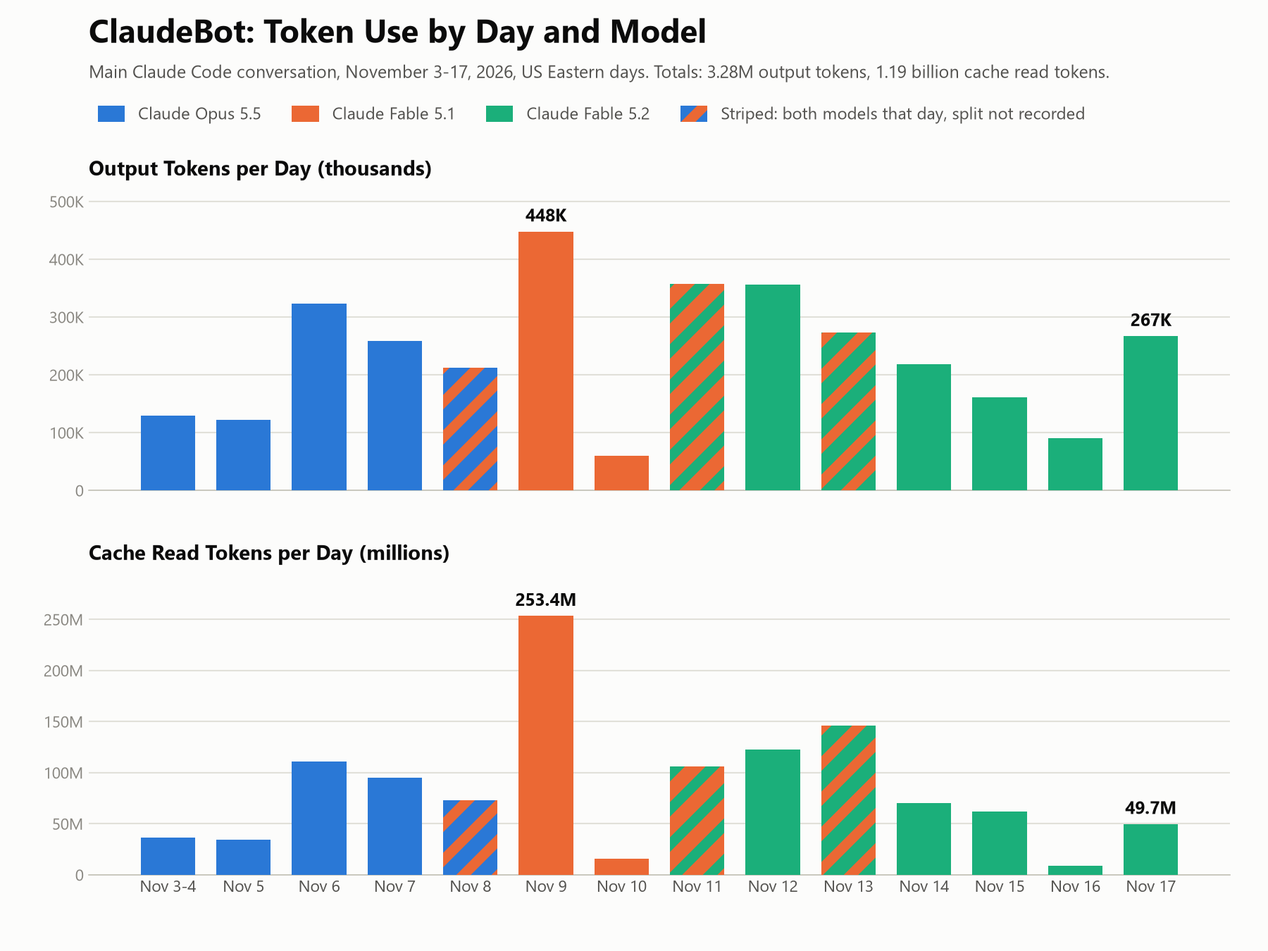
Through November 17 the main conversation made 3,236 requests and wrote 3.2 million output tokens mostly in Fable 5.1 and 5.2. Cache reads, the conversation being re-read on each request, come to about 1.18 billion tokens and dominate the total.
The heaviest day was the day the first assembly failed.
Where It Stands
The v9 arm is printed in black PETG and assembled. Version 10 is designed and printing: The next version will have the turntable move onto two preloaded ball bearings so the servo only has to turn it, the base feet are cut back so a chess board or a sheet of paper can sit flat under the arm, and the elbow is cleared to fold 130 degrees each way.
It is not great at drawing, yet, and is too clumsy to play chess.
The Full Record
The complete process, day by day, with the issue log, the token table, the optimizer setups and the part files as 3MF with all metadata, is published as a CDFAM case study at cdfam.com/case-studies/claudebot.
The parts are open source under CC BY 4.0.
